Crane blocks can be used in accordance with design specifications and are generally intended for tension and pulling. Crane blocks can not be used for towing unless specifically designed and marked for that purpose.
Snatch blocks are generally intended for guiding.
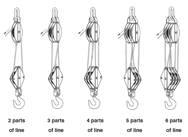
For the use of wire rope blocks, the bearing loads should be taken into account ( see diagram below).
Blocks should be inspected at least once a year by a surveyor for proper functioning and damages.
Blocks should be demounted and cleaned at least every 4 years by a specialist for inspection of wear, hidden damages or beginning cracks and have the blocks tested by an authorized testing body.
The chain hoist is designed for lifting and lowering a load suspended on a chain ( load chain ) by manually actuating a second chain ( hand chain); it is also used to maintain a load suspended. The hoist is secured to a fixed anchor point or to a moving trolley. The hoist is supplied equipped with a load chain and a hand chain compatible for a standard lifting height of 3 mtr. The load chain is formed by one or several strands equipped with a lifting hook on its load-end side; on the other end ( slack strand side), the load chain is secured to a low limit stop itself secured to the hoist. The chain hoist is designed to ensure a minimum mechanical strength of 4 x WLL. The chain hoist is designed and built to withstand dynamic testing at 1.1 x WLL and static testing at 1.5 x WLL.
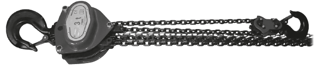
The operator must pull on the right hand strand of the hand chain to lift the load and to lower the load he must pull on the left hand strand of the hand chain.
The load chain must form a direct line from the load hook to the suspension point before the load can be lifted. The hoist is not to be used for pulling lateral.
Do not operate the chain too quickly as this can result in jolts when lifting or lowering a load. The hand chain should be pulled by a smooth, regular action to avoid any swinging of the load.
The lever hoist is a portable manual handle-actuated hoist for lifting, pulling and tensioning, is normally used on a fixed anchoring point or with suspension trolleys. The hoist is supplied with a standard 1.50 mtr length of load chain. The load chain used with the 0.5 ton to 3 ton models is formed by a single strand with a lifting hook at its end. The load chain used with the 6 ton model is formed by two lifting strands and a sheaved lifting hook. The free end of the chain is equipped with a low limit stop. A disengage device allows for fast easy adjustment of the chain using the limit stop. This operation must only be performed with no load on the hoist. The hoist is designed to ensure a minimum mechanical strength of 4x WLL.
The hoist is designed and built to withstand dynamic testing at 1.1 x WLL and static testing at 1.5 x WLL.
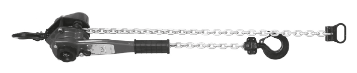
The hoist is operated by means of an actuating handle which is moved back and forth by the operator to lift or lower a load, pull a load, or apply tensioning. The central position is the free stand. In this position it is possible to bring (WITHOUT LOAD) the chain quickly in to the wright position with the use of the hand wheel.
ATTENTION !!! It is not allowed to fasten the load to the low limit stop.
The wire rope pulling hoist is a hand-operated lifting and pulling machine. It is versatile, portable and multi-purpose, not only for pulling and lifting but also for lowering, tensioning and guying.
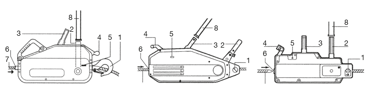
The originality of the wire rope pulling hoist is the principle of operation directly on the wire rope which passes through the mechanism rather than being reeled onto a drum of a hoist or conventional winch. The pull is applied by means of two pairs of self-energised jaws which exert a grip on the wire rope in proportion to the load being lifted or pulled. A telescopic operating lever fitted to either the forward or the reverse lever transmits the effort to the jaw mechanism to give forward or reverse movement of the wire rope. The machine is fitted with a hook or anchor pin, depending on the model, so that it can be secured quickly to any suitable anchor point. Each machine is supplied with a telescopic operating handle, and usually with a 20 mtr standard length of special wire rope fitted with a safety hook and wound onto a metal reeler.
All wire rope pulling hoist incorporate a shear pin system. In case of overload, one or more pins
(depending on the model), fitted to the forward operating lever, shear and prevent further forward or lifting operations. Reverse operation is still possible to enable the load to be lowered or the wire rope to be slackened.
Lifting clamps are applied for lifting and transporting all kinds of steel plates and are made of top quality alloyed steel.
Horizontal plate lifting clamps have specifically been designed for the horizontal lifting and transporting of non-bending steel plates.
The clamps consist of a body, cam and cam pin. The cam also functions as a lifting shackle and ensures that the load is held firmly while it is being lifted.
Horizontal plate lifting clamps should always be used in pairs, or multiples thereof. In the latter case, however, preferably with a load spreader beam. When pairs or multiple clamps are used, each clamp should carry an equal part of the load.
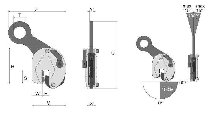
Vertical plate lifting clamps have specifically been designed for the vertical lifting and transporting of steel plates and constructions. The clamps consists of a locking device, a tension spring and a lever. Once the lever has been operated, the safety mechanism provides constant pre-tensioning of het cam on the steel plate, thereby ensuring that the clamp does not slip when lifting force is applied. When a load is being lifted the clamping force on the cam is increased by the weight of the load. The safety system also ensures that the clamp will not be disconnected from the plate as the load is being lowered.
Specifically for a plate lifting clamp is that they function with a by the load generated clamping force. The friction between the load and the cams determine the safety. This is why the clamping jaws have tooth segments. For smooth surfaces which may not be damaged, like a stainless steel-plate, a plastic coating will be used on the cams.
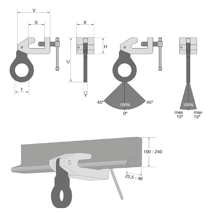
A beam lifting clamp is suitable for lifting and handling steel beams and steel strips (see picture below).
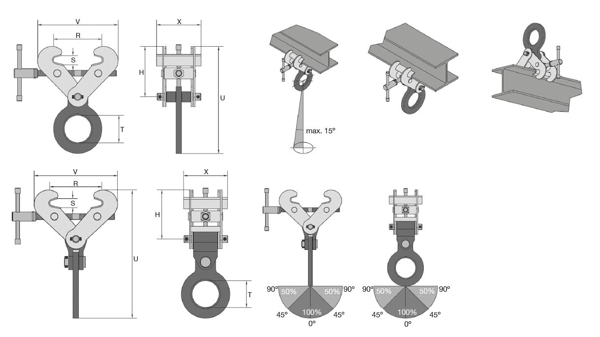
Permissible positions for using the clamps are lifting and handling from a vertical position and lifting work, where the lifting clamp is used as a lifting point. The lifting clamps feature a screw thread mechanism consisting of a threaded spindle and tow spindle nuts. As soon as the spindle has been actuated, this mechanism ensures that a constant clamping force is applied by the jaws. In this way the clamp will not work itself loose from the object. The linked clamping parts ensure that the clamping force continues, which means that the load continues to be held firmly. As there is no cam and pivot arrangement, the object to be lifted does not become damaged.
The safety beam lifting clamp has especially been developed for the lifting of steel beams. Permitted positions for using the clamp are the lifting and transporting of beams in horizontal and vertical position. A special lifting shackle is used to place the centre of gravity of the beam to be lifted directly beneath the lifting shackle. This maintains the balance of the beam, once it is lifted. The lifting clamp features a safety mechanism consisting of a locking device, a tension spring and a lever. Once the lever is operated, the safety mechanism provides constant pre-tensioning of the cam on the steel plate, this ensuring that the clamp does not slip when the lifting force is applied. When a load is being lifted, the clamping force on the cam is increased by the weight of the load. It also ensures that the clamp will not work itself loose from the plate when the lifting force is off the clamp.
The bulb screw clamps (see picture below) have been specifically designed for the provision on a bulp profile of a temporary lifting point. The bulb screw clamp is used individually to create a temporary lifting point on a bulb profile. The lifting shackle may be subjected to a lateral load of up to 45° left or 45° right in relation to the perpendicular and sideways 15°.